

A 2,000W inverter can appear generously sized until a kettle, battery charger or induction hob starts at the wrong moment. Inverter overload causes are rarely mysterious: the inverter is either being asked to deliver more power than its continuous or surge rating allows, or the DC battery system cannot supply that power at the required voltage. For motorhomes, boats and off-grid cabins, identifying which side of the system is limiting is the difference between a quick correction and repeated shutdowns.
What an inverter overload warning actually means
An inverter converts battery DC power into mains AC power. Its overload protection monitors the output demand and, in many designs, the current drawn on the DC input. When a limit is exceeded, it disconnects the output to protect its power electronics, cabling and battery supply.
The warning may be labelled overload, fault, protect or a flashing alarm code, depending on the unit. Do not assume every warning means the same thing. A true AC overload is caused by excessive appliances, whereas low input voltage, high DC cable resistance and battery protection can produce similar behaviour. Check the inverter manual before changing settings or replacing components.
Continuous power and peak power must also be kept separate. A 1,000W inverter may tolerate a 2,000W surge for a few seconds, but it is not a 2,000W inverter. Heating appliances generally create sustained demand; compressors, pumps and power tools often create a short but substantial starting surge.
The main inverter overload causes in mobile systems
Too much continuous AC load
This is the most direct cause. Add up the real running wattage of appliances operating at the same time, then compare it with the inverter’s continuous rating. A 1,500W inverter running a 1,000W kettle and a 600W coffee machine is already beyond its rating before allowing for conversion losses.
Appliance labels provide a useful starting point, but nominal wattage is not always actual consumption. A microwave marked at 800W cooking output may draw 1,200W or more from the inverter. A compact compressor fridge draws relatively little while running, yet its start-up requirement is higher. Measure uncertain loads with a suitable mains energy meter where practical.
For regular use, leave sensible headroom rather than treating the rating as a target. Operating continuously at around 70 to 80 per cent of rated capacity generally gives a more dependable result, especially in a warm locker, engine bay or technical compartment with limited ventilation.
Start-up surge from motors and compressors
Inductive loads are a common source of intermittent trips. Water pumps, refrigeration compressors, air tools, workshop equipment and some chargers can demand several times their running power for a fraction of a second. The inverter may power the appliance once, then trip on the next start cycle when other loads are active.
Pure sine wave inverters are normally the better choice for sensitive electronics and motor-driven equipment, but waveform quality does not eliminate surge requirements. Select an inverter with a documented surge rating and duration that exceeds the appliance’s expected start demand. If the load is essential, test it on the actual battery bank rather than relying only on its running-watt figure.
Battery voltage drops under load
High AC power becomes very high current on a 12V battery system. Allowing for inverter efficiency, a 1,000W AC load can require roughly 95 to 105A from a 12V battery. At 2,000W, the DC current can exceed 200A. The same load on a 24V system requires approximately half the current, which reduces cable losses and makes higher-power installations easier to engineer.
If battery voltage falls below the inverter’s low-voltage threshold during a demand peak, the unit can shut down or report a combined low-voltage and overload condition. This is particularly common with undersized lead-acid banks, partly discharged batteries, cold batteries or a lithium battery whose battery management system has reached a current limit.
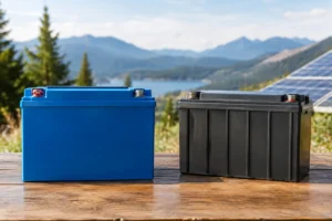
Battery capacity in amp-hours is not enough on its own. Check the battery’s permitted continuous discharge current and peak discharge current against the inverter’s maximum DC demand. A long-life LiFePO4 battery can maintain voltage well under load, but the selected model, BMS rating and number of batteries in parallel must still suit the installation.
Undersized or excessively long DC cables
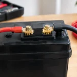
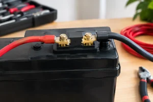
A good battery can still look weak at the inverter if cable resistance is too high. Every metre of undersized positive and negative cable causes voltage drop at high current. Loose lugs, oxidised terminals, poor crimping, an unsuitable isolator or a weak fuse holder add further resistance and can become dangerously hot.
The symptom is often revealing: the inverter works for small loads but trips as soon as a kettle, hair dryer or power tool starts. Measure voltage directly at the battery terminals and at the inverter DC terminals while the load is running. A material difference between the two readings indicates a cable, connection or protection-device problem.
Keep inverter cables as short as installation layout allows and size them for the maximum current, cable length and permitted voltage drop. The fuse must protect the cable, not simply be selected to stop nuisance tripping. Use correctly rated DC fuses, busbars, isolators and crimp terminals designed for the current involved.
Battery BMS or protection hardware is limiting current
LiFePO4 batteries use a BMS to protect cells from excessive current, unsuitable temperature and voltage extremes. If an inverter demands more current than the BMS allows, the battery can disconnect abruptly. This may look like an inverter fault even though the battery protection is operating correctly.
Check both figures in the specification: inverter maximum DC input current and battery BMS discharge rating. A 2,000W inverter on 12V may be inappropriate for a single battery limited to 100A continuous discharge, even if the battery has sufficient stored energy. Parallel batteries can increase available discharge current when the manufacturer permits it and the bank is wired symmetrically, but correct fusing remains essential.
The same principle applies to DC breakers, battery switches and busbars. One underrated component can restrict the whole system.
Other conditions that can trigger a shutdown
Overheating is often mistaken for overload. Inverters reduce output or shut down when internal temperature becomes excessive, particularly in direct sun, sealed cupboards or compartments near an engine. Leave the manufacturer-specified clearance around ventilation openings and prevent clothing, bags or stored equipment from blocking the fans.
A short circuit or damaged appliance lead can also trigger immediate protection. If an inverter faults with a particular appliance but not with comparable loads, inspect that appliance, its plug and extension lead. Do not bypass a fuse or protection alarm to keep power running.
Finally, inverter settings matter. Some units allow low-voltage cut-off, mains priority, power-saving mode and output limits to be configured. An unsuitable low-voltage setting can cause early shutdown, while a power-save mode may struggle to detect a very small intermittent load. Restore known correct settings before assuming hardware has failed.
A practical fault-finding sequence
Start by disconnecting all AC loads and restarting the inverter with the battery fully charged. If it will not start with no load connected, inspect DC polarity, battery voltage, fuse continuity, terminal tightness and any BMS status indication. A persistent fault at no load may require professional diagnosis or manufacturer support.
If the inverter starts normally, reconnect appliances one at a time. Note both the appliance wattage and the point at which the fault occurs. Then test likely high-demand combinations, such as a kettle while a charger is operating or a fridge compressor starting during water-pump use.
Next, monitor battery voltage at the inverter input during the test. Voltage that collapses at the inverter but remains acceptable at the battery points to cabling or connections. Voltage that drops at both locations points to battery state of charge, battery capability or excessive demand. This method avoids replacing a perfectly good inverter when the real limitation is upstream.
For a new installation, calculate the design from the DC side as well as the AC side. A 12V system suits modest loads and compact RV applications. For frequent use above roughly 1,500 to 2,000W, a 24V battery and inverter system can be the more efficient, practical choice, depending on available equipment and charging architecture.
Build for the loads you actually use
The cheapest way to prevent overload is often to avoid running high-wattage heating appliances from batteries. Kettles, electric heaters, toasters and hair dryers consume stored energy quickly even when the inverter is correctly sized. Gas, shore power, a generator or a lower-wattage travel appliance may be the better operational choice.
Where dependable AC power is required, specify the inverter, LiFePO4 battery bank, cables, fuse protection and charging sources as one system. QuantEnergo customers building RV, marine and off-grid installations should base the design on measured loads, realistic simultaneous use and the battery’s discharge specification, not inverter wattage alone.
A correctly engineered system should not merely survive its peak demand. It should supply it with stable voltage, cool connections and enough reserve for the journey, anchorage or evening off-grid.


No comment yet, add your voice below!