

A single 12V 100Ah battery may comfortably run an RV’s lighting, water pump and compressor fridge, but it can become restrictive once an inverter, laptop charging, induction cooking or longer off-grid stays enter the plan. So, can LiFePO4 batteries be connected in parallel? Yes, provided the batteries, cabling, protection and charging equipment are correctly matched. Parallel connection is one of the most effective ways to increase usable energy storage while retaining a 12V or 24V system voltage.
For motorhomes, boats, overlanders and independent power systems, the objective is not simply to add more batteries. It is to build a bank in which every battery shares charging and discharge current predictably, remains protected by its own battery management system, and can be serviced safely.
What connecting LiFePO4 batteries in parallel does
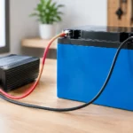
In a parallel battery bank, positive terminals connect to positive terminals and negative terminals connect to negative terminals. Voltage stays the same, while capacity adds together.
Two identical 12.8V 100Ah LiFePO4 batteries connected in parallel create a 12.8V 200Ah bank. The nominal stored energy rises from approximately 1.28kWh to 2.56kWh. Four identical 12.8V 100Ah batteries form a 12.8V 400Ah bank, or around 5.12kWh of nominal energy.
This approach suits 12V applications where existing equipment is designed around a 12V battery system: caravan distribution boards, 12V refrigeration, bilge pumps, lighting circuits and many vehicle inverters. A parallel bank gives longer runtime and, when designed correctly, can also provide greater available discharge current because the load is shared between batteries.
The trade-off is current. At 12V, high-power AC appliances demand substantial DC current. A 2,000W inverter can draw well over 170A from the battery bank once conversion losses are considered. For regularly powering large inverter loads, a 24V system often reduces cable size, voltage drop and stress on connections more effectively than expanding a 12V bank indefinitely.
Can LiFePO4 batteries be connected in parallel safely?
They can, but only when the battery manufacturer permits parallel operation. This is the first specification to check. A LiFePO4 battery contains a BMS that manages cell protection, including over-voltage, under-voltage, over-current and temperature limits. Not every BMS is designed to communicate with, balance alongside or reliably operate in a large parallel group.
Check the permitted number of parallel batteries, the continuous discharge rating, peak discharge rating and charging-current limit for the specific battery model. These values determine whether the planned bank can support the inverter, DC loads, alternator charger, shore charger and solar charging equipment in the system.
A battery bank should consist of the same LiFePO4 battery model with the same nominal voltage and capacity. Ideally, buy and install the batteries together. Identical units have closely matched internal resistance, BMS characteristics and charge behaviour, making current sharing far more consistent.
Avoid connecting a new 200Ah battery in parallel with an older 100Ah unit, even if both are labelled 12V LiFePO4. The smaller or older battery may reach its BMS limits first, disconnect unexpectedly, or contribute less energy than expected. Mixing brands, different capacities, different cell designs or batteries with an unknown service history is a false economy in a system expected to deliver dependable power for years.
Match battery voltage before making the connection
Before joining parallel cables, bring every battery to nearly the same state of charge. This is especially important when batteries are new, have been stored separately or have been used in different installations.
Measure the terminal voltage with a reliable multimeter after the batteries have rested and are disconnected from chargers and loads. The readings should be very close. If there is a meaningful difference, charge the lower-voltage battery separately using a LiFePO4-compatible charger until both units are aligned.
Connecting batteries with significantly different voltages can create a very high equalisation current as the fuller battery attempts to charge the emptier one. That current may trigger BMS protection, damage a fuse, heat undersized cables or place unnecessary stress on terminals. Never rely on a thin temporary lead to equalise batteries.
Do not connect a 12V LiFePO4 battery in parallel with a 24V LiFePO4 battery. Parallel batteries must have the same nominal voltage. If the system needs 24V, use purpose-designed 24V batteries in parallel, or follow the battery manufacturer’s rules for creating and expanding a series-parallel bank.
Correct wiring for a balanced LiFePO4 parallel bank
Short, equal-length battery interconnects are fundamental. Use cables with the same cross-section and length between each battery so resistance is equal. Unequal cable resistance causes one battery to carry more charging or discharge current than the other, defeating the purpose of the parallel arrangement.
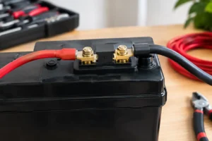
For a two-battery bank, the preferred arrangement is diagonal connection. Take the main system positive from the positive terminal of Battery 1 and the main system negative from the negative terminal of Battery 2. The batteries are then linked positive-to-positive and negative-to-negative with matching interconnect cables. This encourages current to travel through both batteries evenly.
For three or more batteries, use correctly rated positive and negative busbars. Run identical cables from each battery to the busbars, then connect the inverter, charger, solar controller and DC distribution equipment to the busbars rather than directly to an individual battery. This is cleaner, easier to inspect and more scalable than stacking multiple cable lugs on battery posts.
Cable size must be selected for the maximum expected current, cable run length and permissible voltage drop. An inverter cable that is adequate for a small 600W unit may be dangerously undersized for a 2,000W or 3,000W inverter. In marine and mobile installations, use suitably rated flexible cable, quality crimp lugs, heat-shrink insulation and secure mechanical support to prevent vibration damage.
Fuse each battery, not just the bank
Each battery positive connection should have its own correctly sized fuse or DC circuit breaker as close to the battery as practical. This protects the cable if a fault develops between that battery and the busbar. A single main fuse protects the outgoing system cable, but it does not provide the same protection for individual parallel branches.
The fuse rating must protect the cable while allowing normal battery and inverter operation. It should not simply match the largest number printed on a component. Consider the battery’s permitted continuous output, expected surge current, cable ampacity and the interrupt rating required for the system’s available fault current.
A typical high-capacity bank also benefits from a main battery isolator, clearly labelled busbars and a shunt-based battery monitor. The monitor should be installed so all charging and load current passes through the shunt. This gives a far more useful state-of-charge reading than voltage alone, particularly with LiFePO4 chemistry, where voltage remains relatively flat across much of the discharge cycle.
Charging a parallel LiFePO4 battery bank
A parallel bank is charged as one battery bank, but the charger settings must match LiFePO4 requirements. Configure the MPPT solar controller, mains charger, inverter-charger and DC-to-DC alternator charger to the battery manufacturer’s specified bulk, absorption and float voltages. Disable equalisation modes intended for flooded lead-acid batteries.
Total charging current must remain within the combined allowable charge current of the parallel batteries and within the capability of the cabling and protection hardware. Two batteries that each allow 50A charging may theoretically accept 100A combined, but a lower rate can be sensible where solar yield, alternator capacity or heat management limits the installation.
For vehicle charging, a DC-to-DC charger is usually the correct route between the starter battery or alternator and a LiFePO4 leisure bank. It limits current, provides the required charging profile and protects the charging circuit from excessive alternator load. Connecting a large lithium bank directly to an alternator without proper control can shorten alternator life and create unreliable charging performance.
Cold charging also requires attention. LiFePO4 cells should generally not be charged below 0°C unless the battery is specifically designed with low-temperature charging protection or integrated heating. A BMS may block charging in cold conditions, which is protective behaviour rather than a battery fault.
A practical parallel installation sequence
Plan the bank and isolate every charging source and load before beginning work. A disciplined sequence reduces the chance of polarity errors and accidental short circuits.
- Confirm that all batteries are identical, approved for parallel connection and close in state of charge.
- Position the batteries securely in a dry, ventilated area away from direct heat, salt spray and potential standing water.
- Fit individual positive fuses or breakers, then install matched interconnect cables or equal-length leads to positive and negative busbars.
- Make the battery-to-battery connections, checking polarity with a multimeter before connecting the final cable.
- Connect the main positive and negative system cables to the busbars, with the negative return routed through the battery-monitor shunt.
- Programme chargers for LiFePO4 chemistry, then commission solar, shore charging, alternator charging and loads one at a time.
- Under a known load, check cable temperatures, terminal tightness and current sharing across the batteries.
Recheck fasteners after the first charging and discharge cycles. Loose terminals create resistance, heat and voltage drop, particularly in mobile systems exposed to road vibration or boat movement.
When parallel is not the best answer
Parallel connection is ideal when preserving 12V or 24V is necessary, but it is not automatically the best design choice. If your principal load is a large inverter for coffee machines, power tools, air conditioning or electric cooking, moving to a 24V battery and inverter platform may be more efficient. The same wattage at 24V requires roughly half the current of a 12V system.
Space also matters. Two smaller batteries can be easier to install in separate lockers than one heavy 200Ah unit, while a single larger battery has fewer cables, fuses and connection points. Choose the arrangement that fits the available compartment, service access and weight distribution of the vehicle or vessel.
For a correctly engineered parallel bank, the battery is only one part of the answer. Size the solar array, MPPT controller, charger, inverter, cable protection and monitoring equipment as one system. If the intended loads or wiring layout are uncertain, QuantEnergo technical support can help translate daily energy use into a battery bank and charging configuration that will perform reliably away from shore power.
A well-matched LiFePO4 parallel bank gives you more than extra amp-hours: it gives the confidence to stay longer at anchor, park further from the hook-up and use your electrical system without treating every watt as a compromise.



No comment yet, add your voice below!