

A solar controller is the traffic manager between panel and battery. Wire it in the wrong order, omit circuit protection, or select cable that is too small, and a well-priced solar installation can become an unreliable one. This guide explains how to wire a solar controller to battery for 12V and 24V RV, marine and off-grid systems, with particular attention to LiFePO4 battery banks.
Why the battery must connect first
Most PWM and MPPT controllers use the battery connection to identify whether they are operating on a 12V or 24V system. Connecting the solar panel first can prevent correct voltage detection and may leave the controller charging at unsuitable settings. On some models it can also trigger a fault or require a full reset.
The normal connection order is therefore battery first, then solar panel. When isolating the system, reverse the sequence: disconnect the panel first, then the battery. Check the controller manual before commissioning, as its terminal layout, torque values and maximum PV input voltage always take priority.
For a motorhome, boat or remote cabin, this sequence matters because battery voltage is not merely a supply for the controller display. It is the controller’s reference point for charging and protection.
Select a compatible controller and battery setting
Before fitting cable, confirm that the controller suits the system voltage, solar-array current and battery chemistry. A 12V 100Ah LiFePO4 battery requires a controller with a lithium or user-programmable charging profile. A 24V battery bank needs a controller that supports 24V operation and is configured accordingly.
MPPT controllers are normally the stronger option where roof space is limited, panel voltage is higher than battery voltage, or you want the best output during variable light. They convert excess panel voltage into useful charging current. PWM controllers are simpler and can be cost-effective for smaller, matched-voltage solar systems, but panel and battery voltage need closer alignment.
Do not size a controller only from panel wattage. Check both limits shown on its data label: maximum solar input voltage, often expressed as PV Voc, and maximum charge current. Cold, bright conditions can raise a panel’s open-circuit voltage above its nominal figure. The combined Voc of panels wired in series must remain safely below the controller’s PV voltage limit.
For charge current, a 400W array charging a 12V LiFePO4 battery can theoretically deliver more than 30A. Allow sensible headroom and select a controller rated above the expected output. On a 24V system, the same 400W array produces roughly half the battery-side current, which can reduce cable size and voltage drop.
Parts required for a protected installation
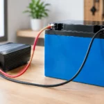
The controller needs a direct, protected route to the battery. The essentials are correctly sized positive and negative cable, a fuse or DC-rated circuit breaker in the positive battery cable, suitable crimp lugs, heat-shrink insulation and a battery isolator where practical. You will also need a PV isolator or breaker between the panels and controller.
Fit the battery-side fuse as close to the battery positive terminal as possible, ideally within 150 to 200mm of the connection where installation layout permits. The fuse protects the cable if it is damaged or short-circuits. It does not primarily protect the controller.
Choose cable by current, route length, installation temperature and allowable voltage drop. Short controller-to-battery runs are an advantage: the controller can only regulate accurately when it sees a voltage close to the actual battery-terminal voltage. For many 20A to 30A 12V installations with a short run, 6mm² cable may be appropriate; higher current, longer routes and marine environments often require 10mm² or more. Calculate rather than guess.
Use flexible, tinned copper cable for boats and exposed mobile installations. It resists corrosion better than ordinary untinned cable. Protect cable passing through metalwork with grommets or conduit, secure it against vibration and keep DC wiring clear of hot exhaust routes, sharp edges and moving mechanisms.
How to wire a solar controller to battery step by step
Start with all energy sources isolated. Cover the solar panels or open the PV isolator, switch off chargers and inverters where possible, and ensure there is no shore charger actively raising battery voltage. Wear eye protection and use insulated tools around battery terminals.
- Mount the controller close to the battery. Choose a dry, ventilated position with room for cable bends and access to terminals. Do not mount it directly above a flooded lead-acid battery, where corrosive fumes may be present. Although LiFePO4 batteries do not vent in normal operation, the controller still needs airflow.
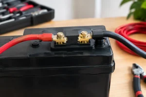
- Prepare the battery cables. Measure the positive and negative runs separately. Crimp terminals using the correct tool, then apply heat-shrink where appropriate. Loose, poorly crimped lugs create resistance and heat under charge current.
- Install the positive fuse or breaker. Connect the controller’s battery positive cable to the load side of the fuse holder or breaker. Leave the battery-end connection disconnected until the negative cable is ready. Size the protection device to protect the cable while accommodating the controller’s maximum output current. A 30A controller commonly uses a 40A-rated cable circuit arrangement, but cable rating and manufacturer instructions determine the correct final value.
- Connect battery negative to the controller. Attach the negative cable to the controller terminal marked BAT- or battery negative, then connect the other end to battery negative or the designated negative busbar. In a system with a shunt-based battery monitor, connect charging negatives on the battery-system side of the shunt, not directly to battery negative, so solar charging is measured.
- Connect battery positive through the fuse. Attach the cable to BAT+ on the controller, then make the final connection at the protected battery positive terminal or positive busbar. Insert or close the fuse only after checking polarity. The controller should power up and display the correct battery voltage.
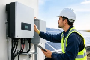
- Set the charging profile, then connect PV. Select LiFePO4, lead-acid, AGM or gel mode as required. If using custom settings for LiFePO4, follow the battery manufacturer’s charge-voltage, float and low-temperature requirements. Finally, connect the panel positive and negative conductors to the controller PV terminals with the PV isolator open, then close the isolator and confirm charging current.
Never connect a solar panel directly to a battery unless it is a very small maintenance panel specifically designed with its own regulation. Standard solar panels can overcharge a battery and provide uncontrolled current under fault conditions.
LiFePO4 charging settings and temperature limits
LiFePO4 offers high usable capacity, low weight and long cycle life, but it must be charged within the battery’s specified voltage and temperature limits. Many 12V LiFePO4 batteries use an absorption or bulk target around 14.2V to 14.6V, while 24V versions are commonly around 28.4V to 29.2V. Those figures are examples, not universal settings.
Do not assume the controller’s lithium preset matches every battery. Confirm the battery data sheet, particularly whether float charging is required, limited or disabled. Equalisation must be off for LiFePO4. A lead-acid equalisation programme can apply an excessive voltage to a lithium battery.
Charging below 0°C can damage many LiFePO4 cells unless the battery has low-temperature charge protection or integrated heating. A quality battery management system may disconnect charging, but the solar controller should still be configured correctly where it provides a temperature or battery-management input. This is especially relevant for winter motorhome storage, unattended boats and external battery lockers.
Common faults after connection
If the controller powers on but shows no solar input, first check the PV isolator, panel polarity and panel Voc at the controller terminals. If it shows a battery fault, measure voltage directly at the battery and again at the controller BAT terminals. A meaningful difference indicates excessive voltage drop, a poor terminal or insufficient cable size.
A controller repeatedly entering over-voltage protection may be set for the wrong battery chemistry or system voltage. If LiFePO4 charging stops unexpectedly, the battery BMS may be protecting against low temperature, high voltage, full state of charge or another battery-side condition. Do not bypass a BMS or replace a fuse with a larger one to force charging.
On boats and vehicles, also confirm the negative arrangement. Some controllers share a common negative between battery, PV and load terminals; others do not. Follow the wiring diagram exactly, especially where a chassis bond, galvanic protection, shunt or DC distribution busbar is installed.
Build for serviceability, not just first-day operation
Label the battery fuse, PV isolator and controller cables with voltage and polarity. Leave a little service loop without creating loose cable, record the controller settings, and recheck terminal tightness after the first few charging cycles. These small details make fault-finding far quicker when you are parked off-grid or anchored away from shore power.
A correctly wired controller turns solar panels and a long-life battery into a dependable charging system rather than a collection of parts. If panel layout, controller limits or lithium settings are uncertain, resolve them before energising the installation – technical support is far cheaper than replacing damaged equipment.




No comment yet, add your voice below!