

A 2,000W inverter can draw more than 180A from a 12V battery bank before conversion losses are considered. That is why an RV inverter wiring guide must start with the DC side, not the 230V socket. A high-capacity LiFePO4 battery and premium inverter will only perform safely when cables, fuses, isolators and terminals are sized for the actual current.
For a motorhome, caravan or expedition vehicle, correct inverter wiring protects the equipment, preserves usable battery capacity and reduces the risk of heat damage in confined lockers. The aim is straightforward: deliver high current over the shortest practical route, protect every positive conductor close to its energy source, and keep AC installation work to the required standard.
RV inverter wiring guide: begin with the system voltage
First, confirm whether the leisure system is 12V or 24V. The inverter must match the battery-bank voltage exactly. A 12V inverter belongs on a 12V battery bank; a 24V inverter belongs on a 24V battery bank. Never connect a 12V inverter directly across two 12V batteries wired in series.
For the same AC output, a 24V system uses roughly half the DC current of a 12V system. This has a practical benefit: smaller cable cross-sections may be possible, voltage drop is easier to control, and larger inverters are more manageable. A 2,000W load at 12V can demand around 185A to 200A from the battery, while the same inverter output at 24V may draw around 95A to 100A.
That does not automatically make 24V the best choice. A modest 12V system with a 600W to 1,200W inverter is often ideal where most existing vehicle loads, chargers and appliances are 12V. For regular use of induction cooking, coffee machines, power tools or an electric kettle, 24V deserves serious consideration.
Calculate current before choosing cable
Do not choose inverter cable by physical appearance or the rating printed on the battery alone. Estimate the continuous DC current using:
DC current = inverter output watts ÷ battery voltage ÷ inverter efficiency
Assume an efficiency of 0.90 for a realistic working calculation. A 1,500W inverter on 12V therefore requires approximately 139A. A 2,000W unit requires about 185A. Add allowance for sustained operation, warm installation conditions and inverter surge demand.
Cable selection also depends on route length. Measure the complete circuit length from battery positive to inverter positive and back from inverter negative to battery negative. Even a short additional run can create meaningful voltage drop at 150A or 200A. Keep the inverter within the manufacturer’s stated cable length wherever possible, often one to two metres from the battery bank.
As a broad starting point for short 12V inverter runs, 35mm² cable may suit around 1,000W to 1,200W, 50mm² may suit around 1,500W, and 70mm² or 95mm² is commonly required for larger 2,000W installations. These are not universal ratings. Cable construction, ambient temperature, bundling, route length and the inverter maker’s instructions all matter. Use flexible, finely stranded copper battery cable with insulation appropriate for vehicle or marine conditions.
Build the DC connection in the right order
The basic inverter circuit is simple, but every component has a job:
Battery positive → correctly rated main fuse → DC battery isolator → inverter positive
Battery negative → shunt, where fitted → negative busbar or battery negative → inverter negative
Fit the main fuse as close as physically practical to the battery positive terminal, generally within 150mm. Its purpose is to protect the cable if it is crushed, chafed or shorted. A fuse at the inverter end cannot protect the length of cable running back to the battery.
The fuse rating must protect the cable while tolerating normal inverter operation and short-duration surge current. It should not simply match the inverter’s advertised wattage. Check the inverter manual for its recommended fuse rating and use a fuse holder designed for high-current DC service. MEGA, Class T and ANL-style protection are common in larger systems, but the correct choice depends on the prospective fault current and the manufacturer’s requirements.
A properly rated battery isolator lets you de-energise the inverter for maintenance, storage or fault-finding. It must be rated for the system voltage and continuous DC current, not just a brief peak rating. Avoid light-duty switches intended for low-current accessories.
Put the shunt where it can measure everything
If the system has a battery monitor, connect the shunt in the main battery negative path. All charge sources and loads should connect to the system side of the shunt, while only the battery negative terminal connects to the battery side. This allows the monitor to record inverter consumption, solar charging, mains charger input and DC loads accurately.
A common wiring error is taking the inverter negative straight to the battery while other circuits run through the shunt. The battery monitor then misses the inverter’s substantial current draw and its state-of-charge reading becomes unreliable.
Where several high-current devices are installed, use correctly rated positive and negative busbars rather than stacking multiple lugs on a battery terminal. Busbars make the layout cleaner, improve serviceability and reduce strain on battery posts. Cover exposed positive terminals with insulated boots or protective covers.
Prevent voltage drop, heat and nuisance shutdowns
An inverter that alarms or shuts down under a kettle load is not always faulty. It may be seeing low voltage caused by undersized cable, loose terminals, an inadequate battery bank or a battery management system reaching its discharge-current limit.
Keep cable runs short, route them away from exhaust heat and sharp metal edges, and support them with suitable clips. Where cable passes through a bulkhead or metal panel, use a grommet or conduit. Do not run high-current DC cable loose beneath seats or through damp storage areas where movement can abrade insulation.
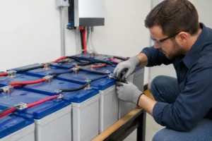
Crimp lugs with a tool designed for the cable size, then use adhesive-lined heat shrink where appropriate. A poor crimp creates resistance; resistance creates heat; heat can damage insulation and terminals long before a fuse operates. Tighten connections to the torque stated by the inverter, battery or busbar manufacturer. Recheck them after the first few heat cycles and as part of routine seasonal maintenance.
Battery capability matters just as much as cable size. For example, a 12V 200Ah LiFePO4 battery may store enough energy for a sizeable inverter, but its BMS must also support the required continuous and peak discharge current. Two batteries in parallel can increase available current and capacity, provided they are identical, suitably protected and connected using balanced cable lengths. Consult the battery instructions before building parallel or series banks.
AC output wiring needs separate attention
The inverter’s 230V output is a different part of the installation. If it only supplies appliances plugged directly into its own sockets, the arrangement is relatively contained. If it feeds the motorhome’s consumer unit, fixed sockets or an automatic transfer switch, the design becomes mains electrical work.
A fixed AC installation should include correctly selected cable, circuit protection and RCD protection, with earthing and neutral-to-earth arrangements compatible with the inverter design. Some inverters switch the neutral internally; others require a specific external arrangement. Incorrect neutral bonding can leave an RCD unable to protect occupants or can cause immediate tripping when shore power is connected.
Do not back-feed an inverter into a campsite hook-up inlet or connect inverter output and shore supply together without a properly rated changeover switch or transfer system. This can damage the inverter, energise an exposed plug and create a serious shock hazard. For any fixed 230V modification, use a competent installer familiar with recreational vehicle systems and applicable UK and European requirements.
Test the installation before relying on it away from shore power
Before loading the system, inspect polarity with a multimeter and confirm every terminal is insulated, secure and strain-free. Leave the inverter switched off while connecting the battery. Some units have large input capacitors and can create a spark at connection; follow the manufacturer’s specified pre-charge procedure if one is provided.
Then energise the system and test progressively. Start with a small load such as a charger, then observe battery voltage and cable temperature under a medium load. Finally, test a realistic high load for several minutes. The cable and terminals should remain cool or only mildly warm. Any hot lug, smell of heated insulation, repeated low-voltage alarm or unexpected BMS shut-off needs investigation before departure.
A well-designed inverter circuit is not about fitting the largest possible inverter. It is about matching inverter output to genuine loads, battery discharge capability, charging capacity and available cable route. Build that foundation correctly and your off-grid power will remain dependable long after the first weekend away.



No comment yet, add your voice below!