

A 24V system is often the point where an RV, boat or off-grid installation starts to feel genuinely capable. It can run larger inverter loads with lower current than a 12V bank, reducing voltage drop and allowing more practical cable sizes. But to configure a 24V battery bank correctly, every major component – batteries, charger, solar controller, inverter, fuses and cable – must be selected for the same voltage architecture.
For LiFePO4 installations, the usual objective is simple: build a bank that delivers the required usable energy, accepts the available charging power and remains protected under the highest expected load. The wiring itself is not difficult. The engineering lies in matching battery capacity, battery-management-system limits and the charging system to how you actually travel, sail or live off grid.
Why choose a 24V battery bank?
At the same power, a 24V system draws approximately half the current of a 12V system. A 2,000W inverter load, for example, may require around 185A from a 12V battery after allowing for inverter losses. On a 24V bank, the demand is closer to 90A. Lower current means less heat in cables and connections, lower voltage loss over longer runs, and a more manageable installation around the inverter.
This matters in motorhomes with inverter-powered appliances, marine systems with long cable routes, and cabins where the battery room is some distance from the loads. It also suits larger solar arrays because a suitable MPPT controller can charge a 24V battery bank efficiently from higher-voltage panels.
The trade-off is compatibility. Most vehicle and marine DC appliances are 12V, so a 24V installation that supplies 12V lighting, pumps, compressors or electronics needs a correctly rated 24V-to-12V DC-DC converter. Do not connect a 12V appliance directly to a 24V bank.
Start with energy, not battery count
Battery capacity is usually stated in amp-hours, but watt-hours give the clearer comparison between systems. Calculate nominal stored energy as:
Battery voltage × battery capacity (Ah) = watt-hours (Wh)
A 24V 100Ah LiFePO4 battery stores approximately 2,560Wh, or 2.56kWh. A 24V 200Ah battery stores approximately 5.12kWh. LiFePO4 chemistry can typically provide a high proportion of its rated capacity without the damage associated with deeply discharging lead-acid batteries, although a sensible reserve still protects against poor weather, unexpected loads and BMS low-voltage cut-off.
Begin with the appliances you will genuinely use. A compressor fridge, laptop charging, lighting, water pump and diesel heater fan may consume a modest daily total. Add an induction hob, coffee machine, air fryer or power tools, and inverter demand rises rapidly. Daily energy use determines capacity; the largest appliance running at one time determines inverter power and battery discharge current.
For example, if expected consumption is 1.8kWh per day and you want two days of practical autonomy, a 24V 200Ah bank offers 5.12kWh nominal storage and a useful margin. If solar charging is reliable and shore charging is available regularly, a smaller 100Ah or 150Ah bank may be sufficient. Space, weight, charging opportunity and budget all affect the right answer.
How to configure a 24V battery bank in series
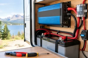
Two matched 12V batteries connected in series create a 24V nominal bank. Connect the positive terminal of the first battery to the negative terminal of the second. The remaining free negative and free positive terminals become the 24V bank outputs.
Voltage adds in series, while amp-hour capacity remains the same. Two 12V 100Ah batteries therefore create a 24V 100Ah bank, not a 24V 200Ah bank. Its nominal energy is 2.56kWh.
Use batteries that are identical in model, voltage, capacity, age and state of charge. Ideally, buy the pair together and install them together. A new battery connected to an older or differently sized battery can lead to unequal loading, premature BMS intervention and reduced service life. This is particularly relevant with LiFePO4 batteries because each unit has its own internal BMS, which may disconnect if it sees conditions outside its limits.
Before making the series link, isolate all charging sources and loads. Check the voltage of each battery with a multimeter. They should be closely matched before connection. Use equal-length, suitably rated interconnect cables with properly crimped lugs, then tighten terminals to the battery manufacturer’s specified torque. Loose battery terminals are a common cause of heat, voltage loss and unreliable inverter operation.
A purpose-built 24V LiFePO4 battery is often the tidier choice where space permits. It removes the series interconnect and simplifies battery monitoring. Two 12V batteries can still be an excellent solution when the available battery locker is narrow, access is limited, or modular replacement is preferred.
Adding capacity with parallel strings
If one 24V 100Ah series pair is not enough, a second identical series pair can be connected in parallel to create 24V 200Ah. Build each 24V string first, then parallel the completed strings. Never take a 24V output from the midpoint of a series pair.
Parallel battery strings need careful cable layout. Take the main positive feed from one end of the combined bank and the main negative feed from the opposite end, or use properly rated positive and negative busbars with equal-length cables from each string. This helps each string share charge and discharge current evenly.
For many mobile installations, one larger 24V battery or a single series pair is preferable to several parallel strings. Fewer connections mean fewer potential faults and simpler fault finding. Multiple strings are justified when capacity requirements exceed the practical size of one battery, but they should be designed rather than added casually.
Match chargers, solar and inverter to 24V
A 24V bank needs a 24V-compatible mains charger, inverter charger or DC-DC charger. A 12V charger will not charge it, while a charger configured for 48V can damage equipment or trigger battery protection. Select a LiFePO4 charging profile based on the battery specification, not a generic lead-acid setting.
Lithium charging voltage varies by battery design and BMS requirements. Many 24V LiFePO4 batteries use a bulk and absorption range around 28.4V to 29.2V, but the manufacturer’s specified values always take priority. Equalisation must be disabled unless the battery documentation explicitly permits it. Temperature-compensation settings designed for lead-acid batteries should also not be applied automatically to LiFePO4.
For solar charging, choose an MPPT controller rated for a 24V battery output and for the combined solar-array voltage and current. Check its maximum PV open-circuit voltage using the panel value corrected for cold conditions. A controller may have adequate output current yet still be unsuitable if the solar string voltage can exceed its PV input limit.
The inverter must have a 24V DC input. Confirm both continuous and surge power, then calculate the likely battery current at full load. A 3,000W inverter can draw well over 130A from a 24V bank during sustained operation once losses are considered. The battery BMS, main fuse, isolator, busbars and cable must all safely support that current.
Protect the bank at the source
Install a correctly sized DC-rated fuse or circuit breaker as close as practical to the battery positive terminal. Its purpose is to protect the cable if a downstream short circuit occurs. The correct rating is based on cable ampacity, inverter demand, battery BMS limit and equipment instructions – it is not selected only from the inverter’s advertised wattage.
A battery isolator provides a clear means of disconnecting the system for maintenance or storage. For larger banks, use covered busbars and separate fused feeds for high-current equipment such as the inverter, solar controller and DC distribution panel. Keep inverter cables short and sized for the actual current and run length; a cable that looks substantial can still be undersized for a high-output inverter.
A shunt-based battery monitor is worthwhile because voltage alone is a poor state-of-charge indicator for LiFePO4. Installed in the main negative path, it measures current entering and leaving the bank, giving a more realistic view of consumption, charging and remaining capacity. Follow the monitor wiring diagram exactly so no load or charger bypasses the shunt.
Commission before relying on the system
After installation, inspect polarity with a multimeter before connecting the inverter or energising any charger. Confirm that the series pair produces approximately 25V to 27V at rest, depending on state of charge. Then test one charging source at a time and observe battery voltage, charge current and any BMS warnings.
Run a controlled load and check for warm terminals, cable heating, unexpected voltage drop or inverter alarms. A thermal check after the first period of high-load operation is sensible, especially in confined RV and boat lockers. Recheck terminal torque after initial use if the battery manufacturer recommends it.
A well-configured 24V battery bank should not demand daily attention. It should provide dependable energy, sensible cable runs and clear charging behaviour. If the system includes high inverter loads, mixed 12V and 24V circuits, or more than one battery string, technical support before purchase can prevent expensive changes once the equipment is installed.



No comment yet, add your voice below!